| HOME | Software | Lotus Cars | DWARF | Kindle | Solar |
In rebuilding the engine/gearbox after the problem in 2012 where the inputshaft coupling broke inside the NG3 I've made some additonal changes.
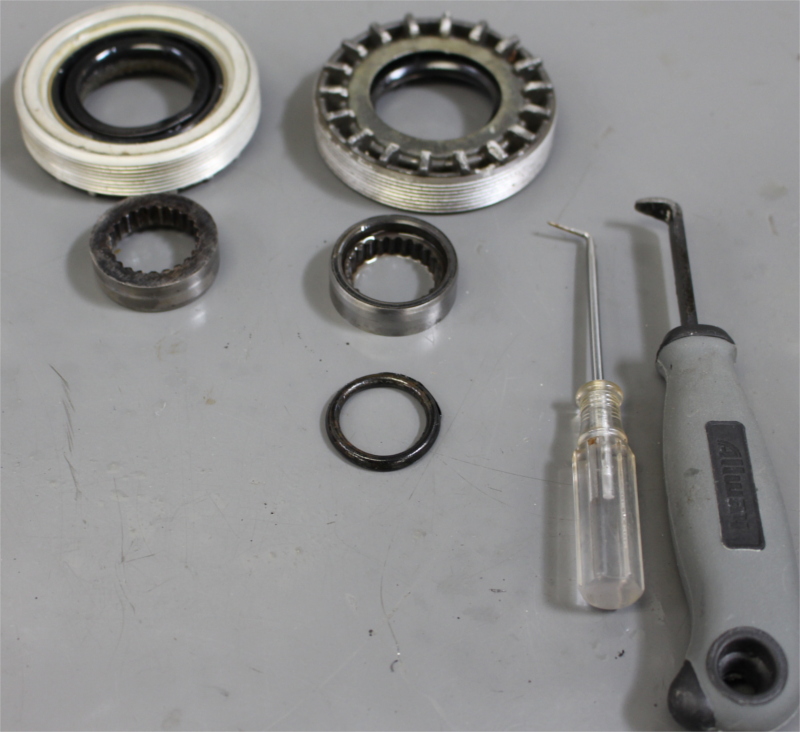
The seals at the big nuts were leaking. Here we have two big nuts (a clean one from NG3 and dirty from 336, really the same big nut). (See big nut tools here.) And two of the inner seals (the NG3 one has some dark coloration and some corrosion etching where the outer seal rides). The Oring pictured was likely damaged by the tools (shown) used to remove the dark steel ring. The nicer looking steel ring is from a 336 and identical to the NG one. I'll use the good looking one.
Removal of the steel seal ring is not difficult. A pointy-tool can get behind the ring to make room for some thing just a bit stronger to move the ring away a bit. All that holds the ring in (once the yoke is off!) is is the seal captured between the ring and the splined output shaft (of course the output shaft has a spot with no splines, right at the bearing).
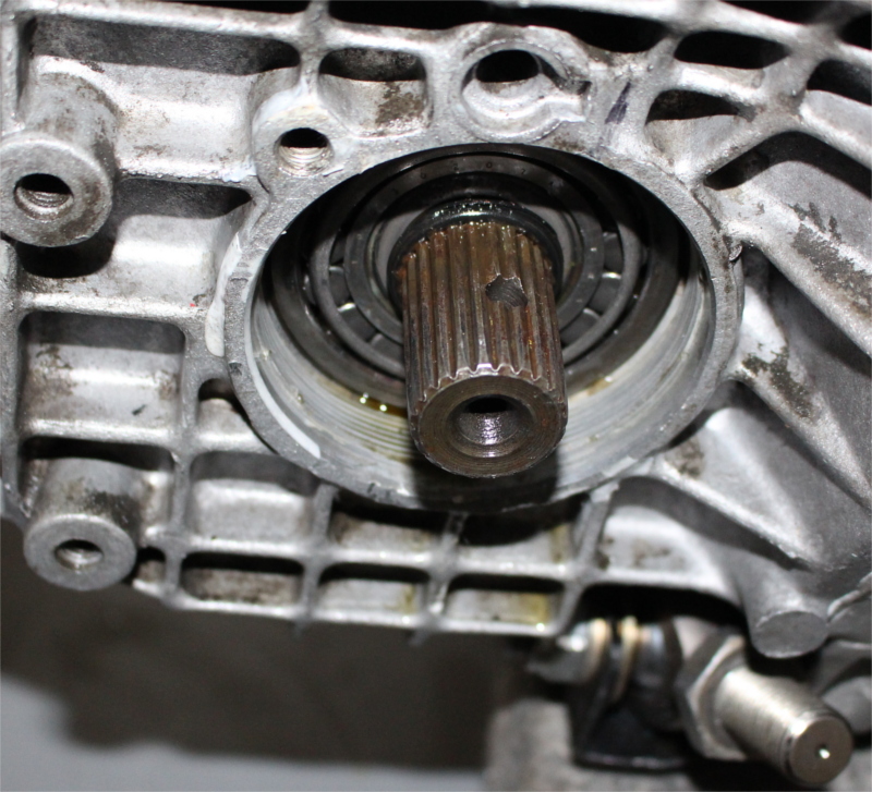
The splines on the output shaft and the steel ring guarantee the ring turns with the output shaft so the Oring sees no motion.
The chamfer on the steel ring goes to the inside. So installing Oring on over the splines (use some tape or some sort of installer to avoid the splines cutting the Oring) and then the big nut and finally the steel ring will avoid damage to the seal in the big nut. I intend to use a Chemical-resistant Viton Oring on each output shaft. From McMaster-Carr assortment 9511K31, 180 pieces.
It's also possible to make a seal protector to go over the steel ring and inside the big nut seal (in case you put the steel ring in first). I think it is possible.
The following is before I removed the old Oring... The visible Oring damage is probably due to my efforts to remove the steel seal ring.
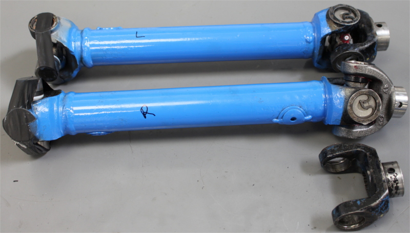
I took the half shafts and the yokes to Driveshafts By Frank Wallace in San Francisco and he balanced them and provided new Spicer U-joints. The yoke end is a stock TC ujoint. The other end uses the same caps but longer arms to match the non-stock outer axle GM yoke (straps and bolts hold the ujoint to the outer yoke on the wheel axle itself). Notice the welded on weights in the picture below. He discovered that the slots in one yoke were machined 0.015in off center. So that the ujoint, when installed with its keeper rings, was not centered on the yoke as the yoke rotated on the transmission output shaft. He commented that Spicer specifies 0.020 inch max as error tolerance and suggested I get another yoke. This was a yoke that came with the car and was machined wrong at the factory (or wherever Lotus had the yokes machined). With the car in the air, idling (some years ago), I could see that the axle was made to wobble by the yoke, but did not understand what was wrong... Fortunately r.d.enterprises had a new yoke arriving within days (when I called) and you see the new one installed on the axle (below). You cannot see, but the new yoke has two through-holes, not just one. That means that it fits 336, 352 and 356 gearboxes (not S1/S2, just TwinCam). The old one is shown too.
The reason the transmission inputshaft coupler broke was a combination of too much compliance at the engine and too little compliance at the gearbox rear when a shift from 3rd to 4th with a fast clutch release twisted the bellhousing on the gearbox. In addition, the locator rings at that joint were very thin -- not stock. So based on advice by Barry Spencer I made the motormount have a positive limit.
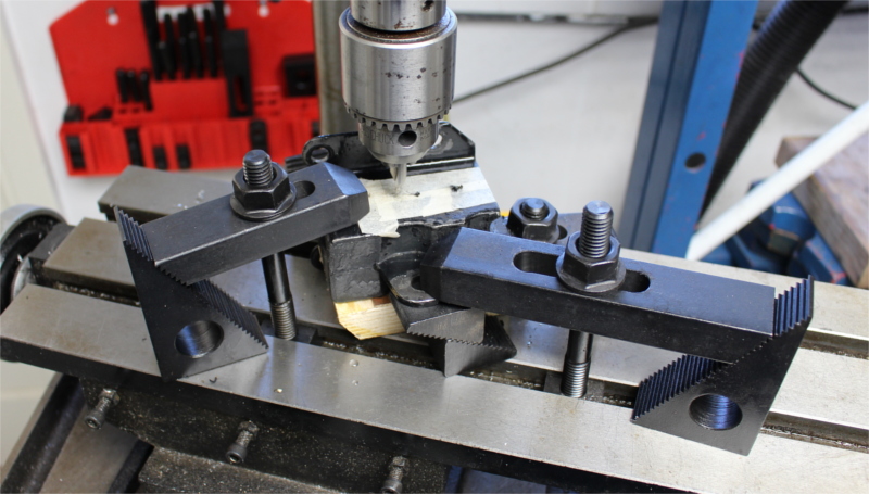
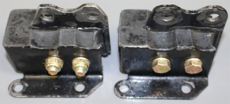
Stock motor mounts are fairly stiff, at 5000lb/inch. Uprated (fully rubberized) mounts as you see below are stiffer at 12000lb/inch, but I added a positive stop.
First, using the setup pictured below with the starter bit, I started a hole and then drilled 3/16in, 1/4in, and finally 3/8hole through the entire assembly (2 holes each mount, all done identically). Then I use 25/64in drill through the rubber each side (not the center plate) to get enough rubber removed that a 3/8in NF bolt could be turned through the assembly. And finally, I used a 31/64in drill to just barely go through the side plates. that means a bolt through the assembly is narrower than the holes in the side steel by about 0.110 inch so 0.055 inch on every side of the bolt is the compliance. The weight of the engine at rest will take up about 0.023 of the gap (maybe a little less as the mounts bolt to the frame at 11 degrees). I hope the remaining compliance is enough to avoid harsh vibrations for everyday driving. The nuts on the bolts just take up the slack, they are not tight. The 3/8in. bolts are AN airframe bolts and all the threads are outside the mount (inside the nut).
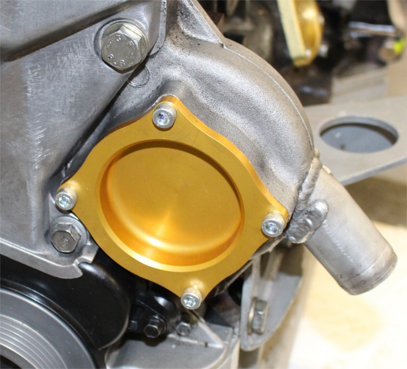
Since the engine's coolant is pumped by a Davies-Craig electric pump the insides of the engine's water pump served no purpose. Dunnell Engines had a very nice replacement. Shown below.
The welding on the waterpump is by John Zender and he also created tubing to mate up perfectly with a minumum of tubing and hence of weight of water. This reduced the coolant by about a gallon, saving eight pounds.
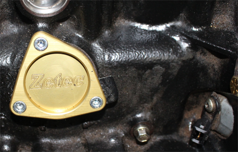
Since the steel engine block vent rarely does anything even on a Ford Focus I deleted it in favor of the much lighter cover pictured below. Dunnell Engines supplied this too. Shown below.
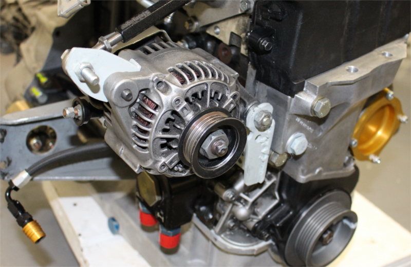
The old alternator drive involved 10 pounds of brackets and pulleys. The new one has a smaller (much lighter) crankshaft pully and very little bracketry. The drive belt itself (not pictured) is a 305K4 4-rib belt (K is the rib profile, and 305 means 30.5 inches long). (The tubing and brass under the alternator is an oil line with dry-break connector so the pressure guage connection and oil-pressure warning sensor can be mounted on the frame)

This work is licensed under a
Creative Commons Attribution 4.0 International License.