| HOME | Software | Lotus Cars | DWARF | Kindle | Solar |
Updated the dashboard layout: moving the oil temperature gauge from glove box to dash, moving the fuel pump switch to the plastic console, and moving the three non-standard warning lights into an instrument-like pod next to the oil temperature gauge.
I tossed out the original wiring and did it all from scratch. Using Enos Custom Components Black Box as the main fuse panel. The wires are mostly from Enos and have baked on labels naming their function. Not all are so labeled though, so I use a label maker for some. The Enos wires have very tough insulation and are much higher current capacity than stock. I guess Colin Chapman would not have approved of the weight of the wires!
We start with a mention of a pdf of the wiring diagram. I wrote it in LibreOffice Draw (A free application using a documented format) and exported this to pdf. This is the wiring pdf. It has some pages that look, um, less than wonderful. My curvy lines drawn with the mouse/trackball don't come out too well. Thanks to Dean Caccavo as it was his wiring diagram that showed me a way forward and inspired me to document the wiring --- he is in no way responsible for my mistakes!
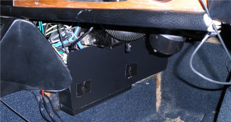
The wiring by the black box could always be tidied up a bit more (as the following pictures make clear!).
The first picture is of the wiring as installed. The Wires are not visible from the seat, you have to assume the Lotus Position to see them, though the panel cover and the extension I riveted to it is visible. Picture updated 29August2012
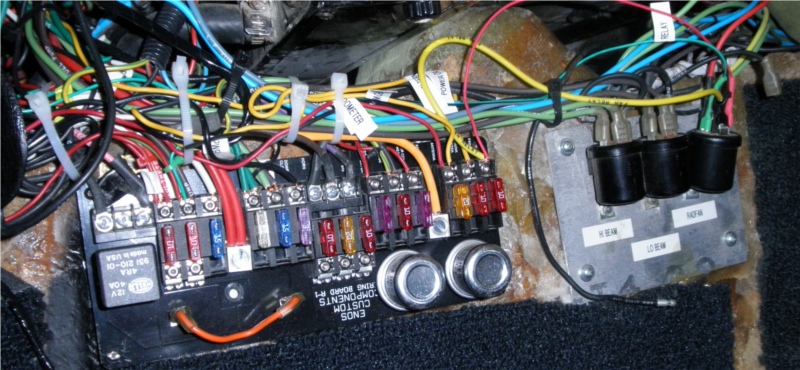
The following photo shows the 18 fuse positions and the components. The relays for the front lights and the radiator fan are at the right of the fuse panel: now the switches on the dash just operate the light/fan relays. The relay panel looks like it screws to the thin fiberglass. It does not. I fiberglassed small rectangles of aluminum with threaded holes to the body there and used very short screws into the aluminum. All the things in here that fasten to the body are done in that fashion. Picture updated 29August2012
The dashboard is sort of original (it needs replacement with good wood and veneer) and looks pretty stock except instead of a radio there is a black panel with two instruments.
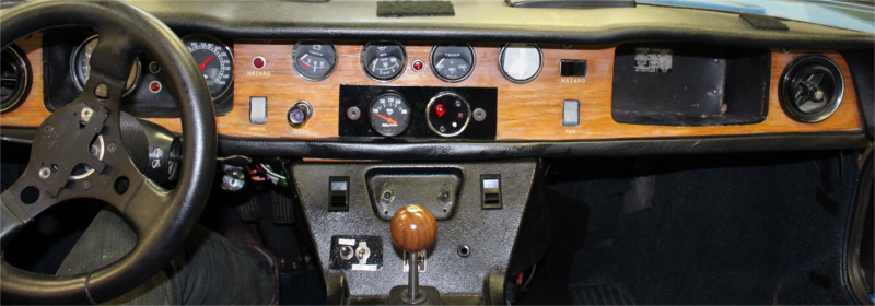
On the console left of the gearshift: The pump switch is quite handy when working on the electrics as one can then turn off the power hungry fuel pump motor while the ignition is on.
The horn button is left of the gearlever as that makes it unnecessary to have wiring inside the steering wheel.
The nonstandard extra warning lights are in the "instrument" below the water temperature gauge. The large red light goes red when the REVEFC water temperature sensor (bought from Burton Power) detects excessively hot coolant. The small red LED to its right goes on when the Davies-Craig coolant controller detects an error condition. Having both red lights means that even if the coolant controller loses power there is an over-temperature sensor working. The white LED to the right of the reds turns on when the knock sensor detects what it thinks is engine-knock. The bolts connecting the panel go through holes once used for radio controls and are cute items intended for furniture. Their nuts behind the panel are aluminum items I created to save weight :-)
The ventilation fan switch on the dash is not connected and the fan itself is not installed in the front trunk plenum.
The window motor switches are directly wired to the motors, but these are industrial switches and both sides of each switch wired in parallel to reduce current through each switch path. Even though there is considerable resistance in the window movement the stock window motors are so strong the windows move very smartly. It's crucial though that the wires are large enough diameter that the wires do not limit the current.
The right hand hole (a leftover from a 1970's air conditioner installation that was ill-advised: the aircon power used the fan belt, thus pulling on that delicate Lotus TwinCam water pump area) is just left empty (with grommet there just for appearance).
The ashtray is in a plastic parts bag, not on the car :-)
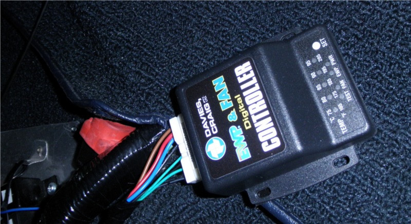
Near the drivers right elbow (held on with velcro) is the Davies-Craig EWC digital coolant control module. It is difficult to see from the driver seat but the EWC warning light on the dash is easy to see. The red top near the controller is on an inertia switch for the fuel pump so in case of a crash (yikes) the fuel pump will stop.
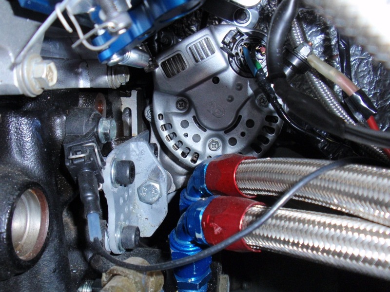
Wiring the alternator is pretty critical. A Toyota has 3 wires (I,S,L) plus a post. The power post goes to the battery + terminal (in my case I wired it to the starter + as that then goes to the battery). The other 3 can be pretty thin wire. 18 Gauge should suffice, though as usual I used heavier wire.
The L wire is for a light on the dash. I ignored it and you can too. The I wire goes to the ignition. The I should get electricity when the ignition is on (it need not when the starter engaged). The S (sense) wire is critical. This should go directly to the battery plus, or as close as possible. It should not go thru any connectors or junctions. The voltage it sees needs to be the real voltage in the wiring harness, not the voltage after various voltage drops through connectors. It needs that highest voltage, because that is the voltage it uses to decide when to stop charging. If you just connect S to a local + point (such as the alternator power post or a random close + wire) you will not charge the battery correctly (you may be overcharging or undercharging depending on how you wire up the sense connector). The term used for the S wire is 'remote sensing'. In my case the closest I felt comfortable with was right at the emergency electrical switch (the on/off is at the drivers left shoulder).
To connect the 3 wires get the proper round connector for the alternator. Then once you connect that correctly to your harness you will not get the wires wrong connecting the alternator. Call Northwest Regulator Supply on the phone and order the Repair Harness, Toyota, 3wire (PN 050-012159). Named AmFor Electronics by 2015 but the same part number works. In the US it is 1-800-242-6367. In July 2008 it was $8.75 plus shipping.
The post is that nut sticking up and right near the 3wire connector.
As of 2015 the alternator mount is very slightly different as I improved the alternator drive, but the wiring is unchanged.
Other alternator pictures are here

This work is licensed under a
Creative Commons Attribution 4.0 International License.