| HOME | Software | Lotus Cars | DWARF | Kindle | Solar |
The 336 transaxle of a Lotus Europa has a little 90 degree speedometer drive that plugs into the rear. A plastic gear inside the transaxle turns the speedometer drive [see the gear and a bad one]. In turn the flexible speedometer drive shaft is turned by the 90 degree drive output shaft. [On my car it drove a very short shaft to an electrical pickup for the TPI electronic speedo till in 2009 I removed the angle drive when I installed the Zetec engine, but stock the gear and angle drive powers a very long flexible shaft up to the speedometer.] Because the 90 degree drives cannot be lubricated and are 35+ years old I decided to take mine apart and see if it was still properly lubricated. I was encouraged by a report on the lotuseuropa mailing list that someone else had done this and managed to get it back together!
Though I set the angle drive aside I am keeping this description so folks using a stock speedometer can see how the gear and the angle drive work.
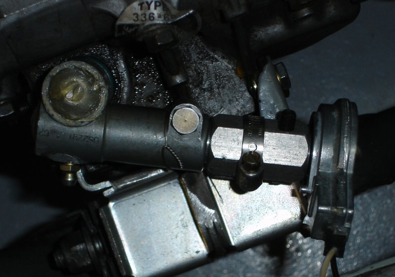
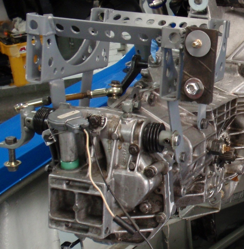
Here is the final assembly, in place. Notice the output is electrical, not a mechanical cable drive! In March 2007 someone on the Europa list noticed I could have omitted the angle drive and simply made an adapter that plugs directly into the gearbox. Well, I did not think of that at the time... So before some time in 2009 it looked like:
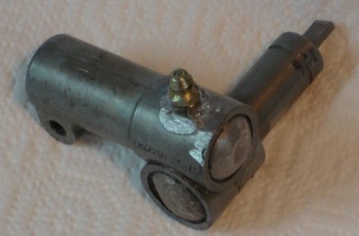
And the reassembled drive, all by itself.
Then a picture of the almost-ready-to-reassemble drive-gear.
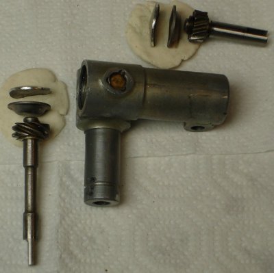
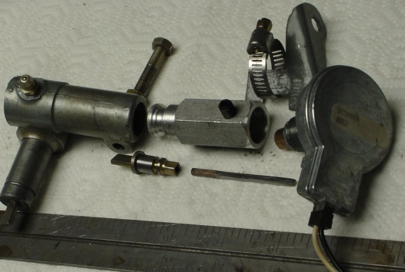
Each of the two gears is positioned by the aluminum housing at one end (on the shafts) and has a small well-made washer interposed between the housing and the gear. A very tiny woodruff-key locks each gear to its shaft. A tiny steelwire is formed in a slot near this end of each shaft to retain the gear at the top. Above that is a dished steel plate that provides the end support (limiting movement of the shaft and providing an end-bearing surface). And finally is a welch-plug sealing it in and preventing the end support from being pressed out). Welch plugs are also called freeze plugs or cup plugs. I believe the original welch plugs are steel of a nominal 20mm in diameter and about 1.1 mm thick. (the plug is a bit less than 20mm before installation, and after the end is punched in with a hammer blow it's a bit above 20mm).
The grease in the housing was in very good shape (considering). Much of it clean. Plenty of it present. It was a sort of dark mustard color (vaguely recalling this as one standard grease color for some kind of grease). The gears in the housing seem to be made of steel. The input gear is 6 teeth, the output gear is 12 teeth, so it is a 2-to-1 reduction gearset.
Getting the original welch plugs out was a puzzle. I finally used a Dremel cut-off wheel and made numerous slots in the plug till it could be gripped with a needle-nose pliers and twisted out easily.
A welch-plug manufacturer web site suggests using a hammer and a drift somewhat smaller than the diameter as a punch to install a welch plug.
The small brass circle in the housing is a flat piece with peened-over aluminum holding it in. One guesses that was used to lubricate everything at initial assembly. After agonizing over what to do, I punched out the brass disc and used Alumiweld to fill in the hole. I then drilled and tapped that filled-in area for a standard grease fitting (#3 drill, grease fitting threads 1/4-28).
Since I had no luck finding a commercially-made welch plug correct for this application I resorted to making a pair myself. I made a crude tool set to start. It's simply a round base piece of steel with a 3/4inch hole bored through it and a punch of aluminum with a rounded end.
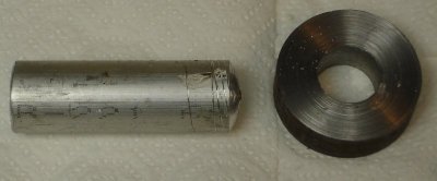
Interposing a 1 inch square of .040 aluminum (it has to be soft enough to take a set) between the punch and the base and hitting with a large hammer forms a cup plug. Then trim with snips and file to make it round-enough and small enough to fit in the gearbox ends. The originals were NOT tight on my car. And certainly did not seal. So it's not necessary to get a seal. Of course that also means it was not ever a good idea to use high-pressure anything to clean in the area of the speedometer drive gear! Fortunately in normal service it's well protected from any source of high pressure water spray by the nearby frame and gearbox parts. But not the end of the story, read on.
The welch-plugs I was able to find on the web were rather too thick. Not meant for a light aluminum housing seal.
The (hidden in the photo) side of the base I machined out to match the inside diameter where the plug goes. My initial plugs were inadequate: when bashed they did not expand enough to seem like they would stay in very well. Making these turns out to be quite tricky.
The ones I actually used for final assembly I made with more steps:
The final cup-plugs after making before assembly were about 5mm deep (20mm wide). Inner dimension cup plug must fit in (before bashing to expand): 20 mm. After expansion, room where slot is for plug to expand into: 21.4mm (this is the diameter inside the cup-plug slot). Height of slot for plug: 1.4mm.
The final plugs I made are, IMO, too dome-like. They should have had a small flat edge-ledge that would slip nicely into the slot. I'm not a very happy camper, but don't think I can make a better part! At least not without LOTS of effort making rather sophisticated tooling. It also takes several minutes of irritating fettling to get things to fit. Not a job I want to repeat soon...
Having revised the speedometer drive gearbox, I needed to get it to turn the electronic speedometer (TPI/Daytona) sender (the Ford style, which I arbitrarily chose when ordering the speedometer).
My initial attempt was to shorten the standard 25 foot drive cable to about 6 inches and fiberglass a holder to the inside rear behind the gearbox. That sort of worked for a while. But it was awkward as the short flexible drive piece remaining had to go through a 80 degree turn (and after a short while it failed to work...).
So I rebuilt the electronic-sender-drive by making a housing of aluminum that fit both the Renault speedo drive and the Ford sender. And a small steel piece that bolts to the gearbox rear mount to support the weight. The (2 inch long) square drive pin I made like a blacksmith would: hammer and anvil treatment of a piece of steel wire.
Here is the final assembly, in place. Though it's hard to see the allen-screw there is one near the sender to ensure the sender does not turn. I added safety wire here as insurance that things won't come apart. By March 2007 the allen screw had fallen out and vanished, but it really made no difference, nothing could come apart! There is no flex, it's a rigid straight assembly attached solely to the gearbox at both ends.
In October 2007 for the Zetec project I went to a direct-sender-drive and omitted the angle drive. See The Zetec speedodrive details.
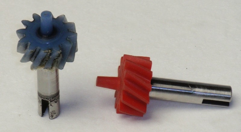
This little gear drives the stock speedometer (providing the input to the angle-drive). The gear is inside the rear housing. If the angle-drive or the very long stock cable seizes up the plastic gear will strip part of its teeth.
The blue plastic gear below is original Lotus and stripped. The red one is new, unused, a result of Steve Veris' effort in 2005 to make new ones available (I have not heard of any available in 2010).

This work is licensed under a
Creative Commons Attribution 4.0 International License.