| HOME | Software | Lotus Cars | DWARF | Kindle | Solar |
Barry Spencer of Spencers Motorsports installed an NG3 gearbox for me and I picked up the completed car February 10,2012. I could imagine all the design and installation taking me a year and I was unwilling to spend the time so I had Barry do the work, and as you will see by the pictures below the results are very very nice. Lots of pieces had to be designed and manufactured in the process. It is not a simple project.
The gearbox is an NG9 (lets just call it an NG3) which is a much stronger version of the original 336 gearbox. It is also heavier. The strength does not come for free! The NG3 was used with 2 to 3 Liter V6 engines, so my 2.0 Liter Zetec poses no threat to its integrity. The gearbox was converted to Europa-style output shafts by Richard Winters in England. The original purchaser in the US sold it to me. So far the NG3 does not leak a drop. A dry transmission is sooo nice after years of cleanup after the 336 gearbox leakages.
Here are some topics:
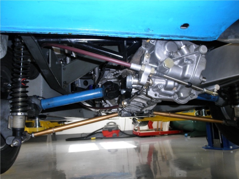
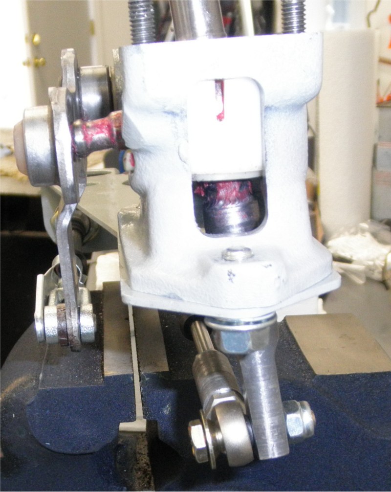
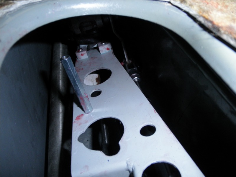
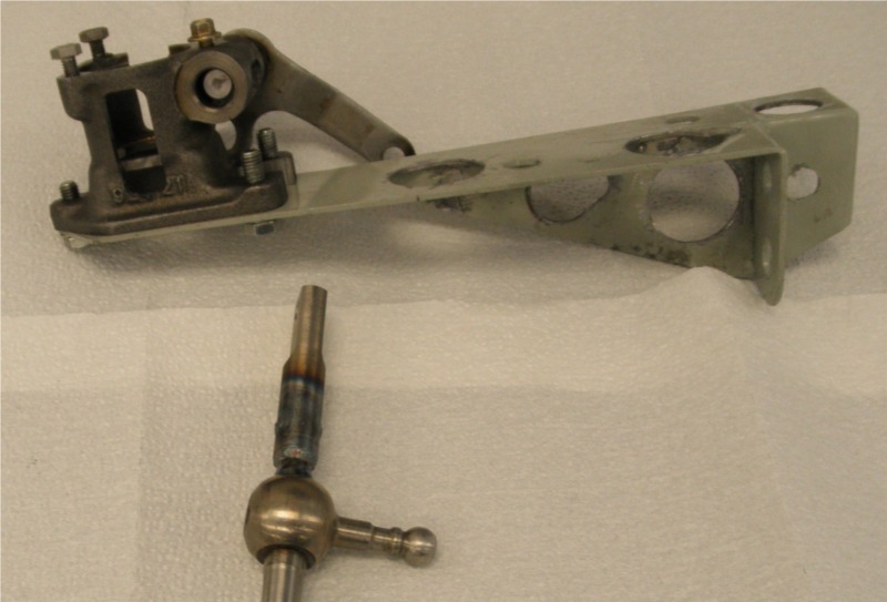
As part of the project I used David Lindemann's cable-shifter (that project was bought by several of us on the lotus-europa yahoo mailing list) to replace the original Lotus tubes and rod-ends. On the track in some corners the tubes would flop around just a little and the cables won't do that. In the first picture below notice that the cross-shaft in the rear housing has just the side-shifter. That's how Richard Winters set it up. The critical aluminum piece which does the actual movement of the cross-shaft is clamped to the cross-shaft but also has a roll-pin to keep it from moving.
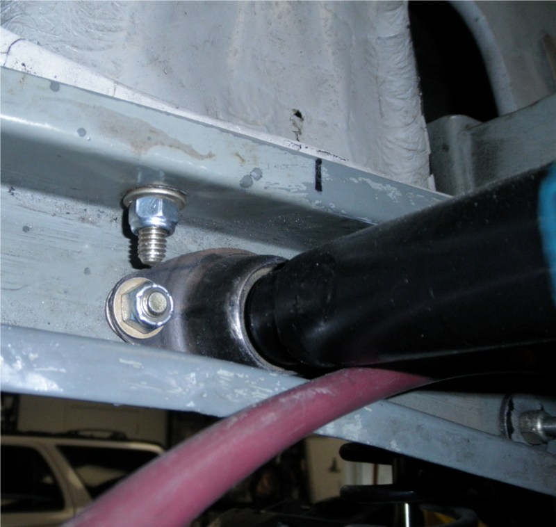
Here is the lower left (part of it) after revising the fore-aft movement connector. The above version of the attachment of fore-aft shifter cable to the aluminum piece unscrewed itself half way in just an hour or two of local driving so just before the April 4 2012 trackday I drilled through (0.25 inch diameter hole) and used a couple of PegasusAutoRacing rod end retainers and an aluminum spacer with a grade 8 bolt to hold things together. This worked well.
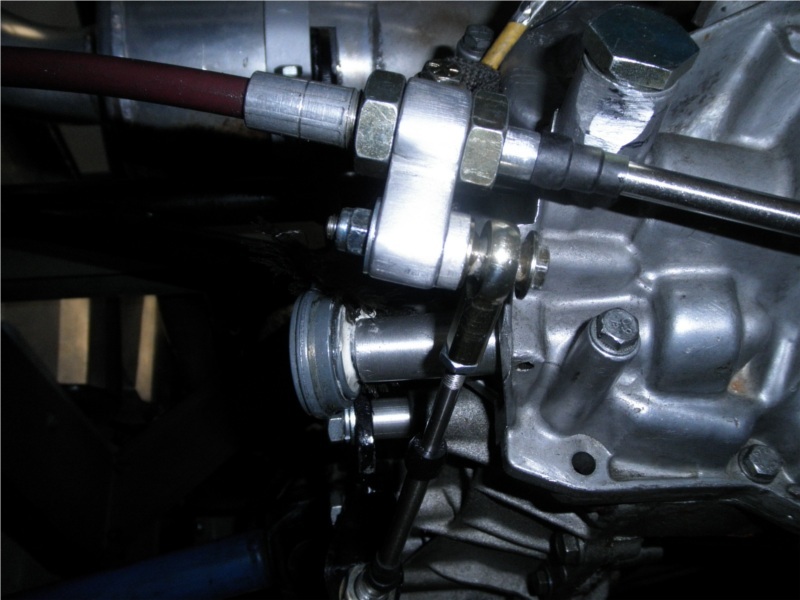
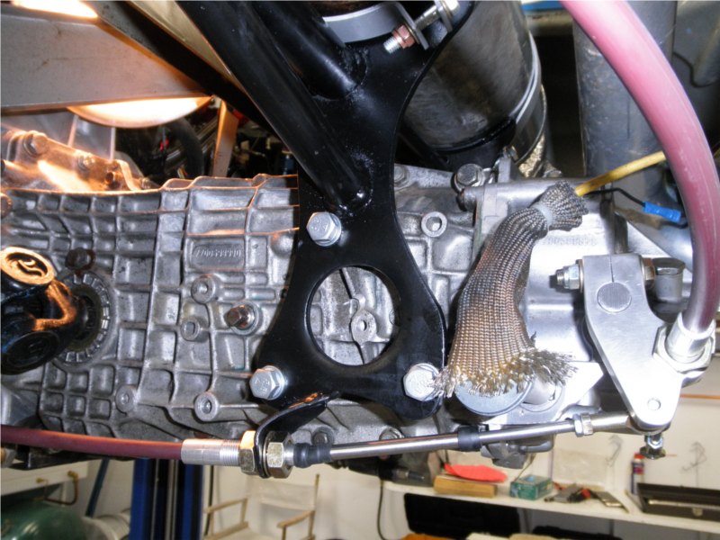
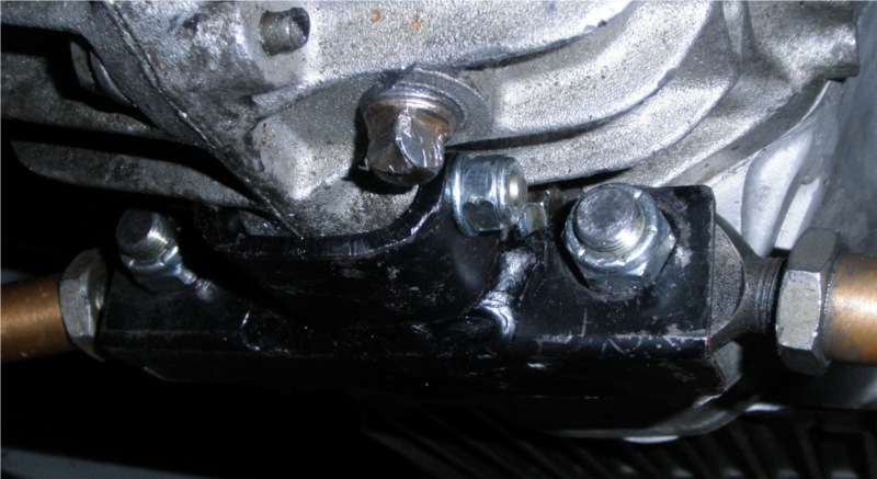
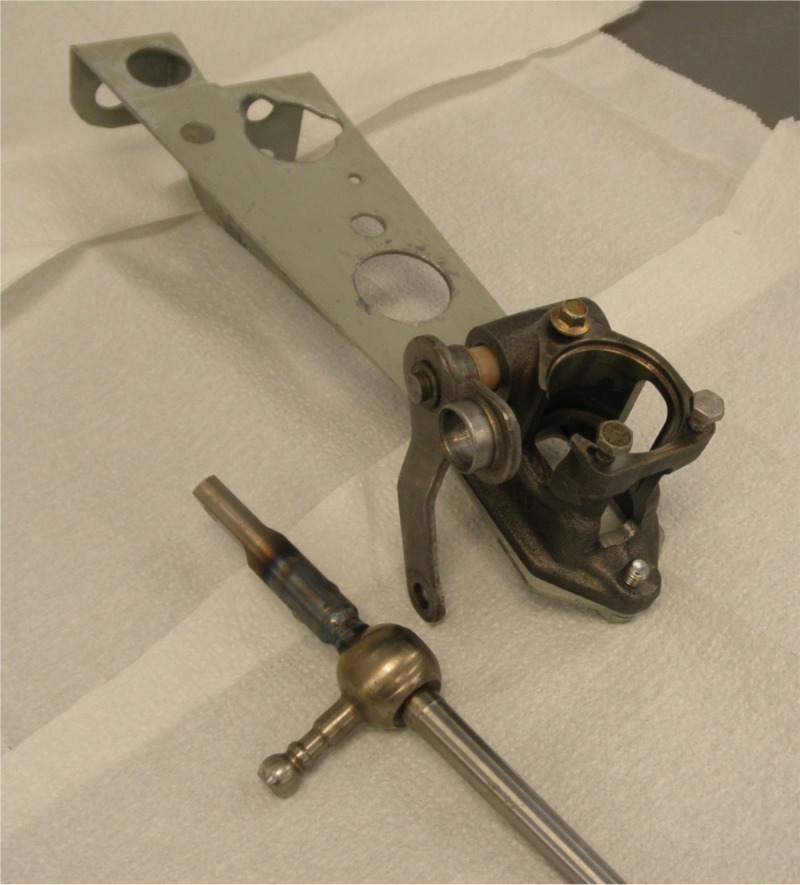
Here is the right side of the shifter and gearbox.
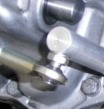
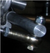
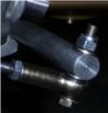
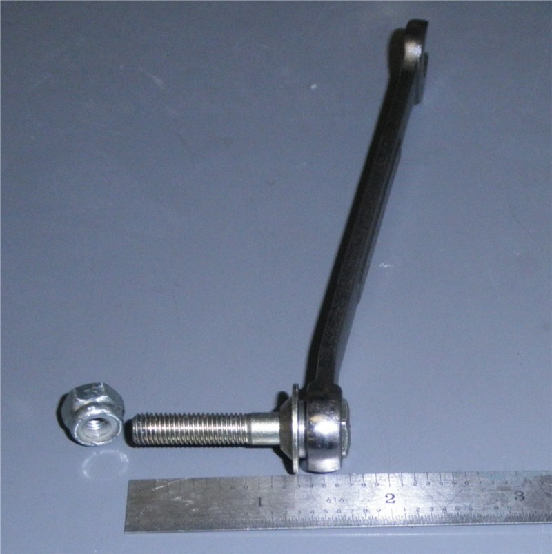
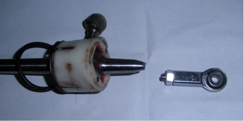
Notice the cable shifter end in the above picture and isolated just below. That original version had a tendency to work itself loose. The following are the original, second and then the final (I hope) versions of the end of that cable. Notice that the rod end now has a smaller stand-off from the support rod (which reduces angularity at the cross shaft attachment, a nice side effect).
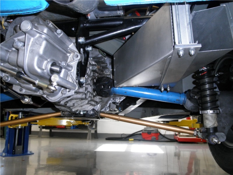
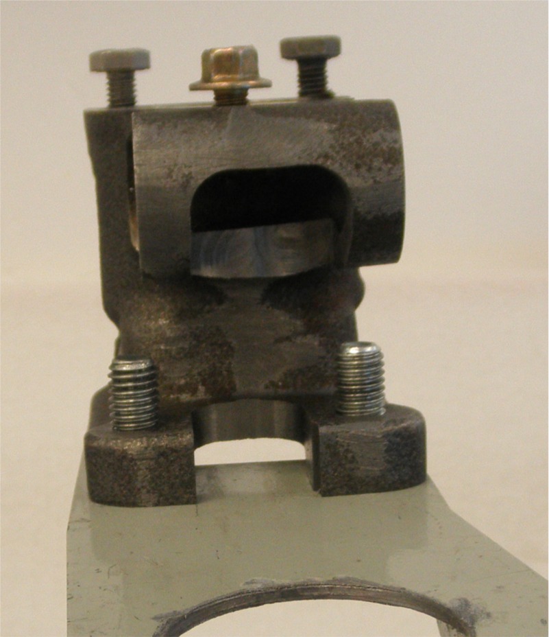
The rear transmission support does three jobs. It supports the ng3, it has a support for a shifter support, it supports the exhaust. The Shifter connection to gearbox shows parts of the rearsupport. The following show more detail of the rear mount itself.
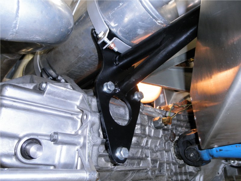
The transverse link mount was constructed from scratch like the stock 352 or 365 Europa mount, but matching the wider case at the bolt points so the gearbox case did not have to be machined at all. That nasty old bodged drain plug got replaced by a nice shiny new one from Richard Winters.
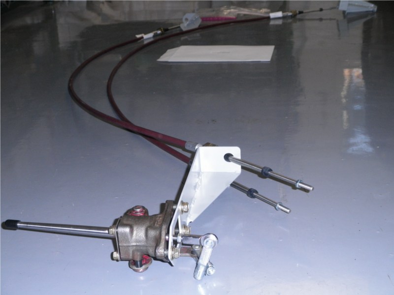
We'll start with an overview. Here is the shifter as Dave Lindemann shipped it, not fully assembled here, just sort of placed together so you can get an idea of the pieces. Some of the pieces were made by midwestcontrols.com, the shifter casting was from a Toyota Corolla manual transmission floor shifter (88-92), and some of the pieces were designed and manufactured by Dave Lindemann. I'm assuming you have DL's instructions. I don't reproduce any of that information here.
Once the shifter broke (story told below) I used a suggestion by Dave L and Tim E and had my shifter modified as in the following picture. A new piece was welded onto the shift lever bottom and large holes were cut in the shifter casting and the steel brackets. Partly the holes saved weight, but the holes in the steel brackets also made assembly in the Europa tunnel much easier. The big holes near the back of the assembly make it a doddle to screw on the big nuts and adjust them and tighten them because you can see and touch all the big nuts easily. And use both a finger and thumb to get them finger tight. The other holes simply make it easier to see into the tunnel while working.
I assembled the modified shifter parts on the bench (with cables loosely attached. Note the rod-end and its bolt. I found I could not get a grip on the bolt in the tunnel. No decent access. Solution below.
Simply using a longer bolt and a steel bushing gave something I could get a tool on in the tunnel. The flared washer is a Pegasusautoracing.com part which gives full motion to the rod end but prevents the rod end from falling off completely even if the rod end fails. Here is the longer bolt and the bushing/washer.
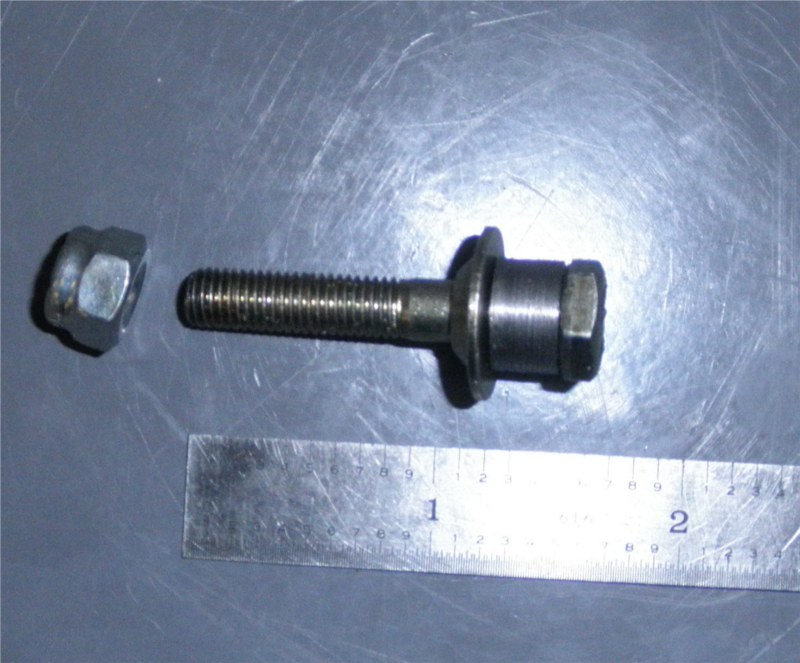
And here is the same bolt with a wrench on it Even out of sight in the tunnel it's easy to get a box end wrench to stay on. One could also use a small-ish vice grip.
Lets just throw in a clear side shot of the actuator that goes on the transmission side-shifter lever.
Now we get to pictures during build-up of the assembly in the tunnel. Note that before inserting the assembly (and the cables are not attached at this point) screw in and tighten all 3 bolts (the ones that screw into the bottom of the shifter casting) fastening the casting to the plate the cables will fasten to. I'm assuming now that you have created the holes in the top of the tunnel as Dave L's instructions tell you to. You need all those created and correct. And one more secret (not in Dave L's instructions). After you insert the shift lever and the side levers in place (on the bench) use a 6mm short screw and a 20mm (approximately) washer in the rear-most of the 3 holes in the casting. Barely finger tight. The washer overlaps the nylon bush on the shift lever. Now you can pull up on the shift lever while moving things in the tunnel and the shifter won't pull out.
And you really don't want to pull the lever and nylon out of the shifter casting inside the tunnel. You can get the shifter and nylon back in but it is a hassle you don't need.
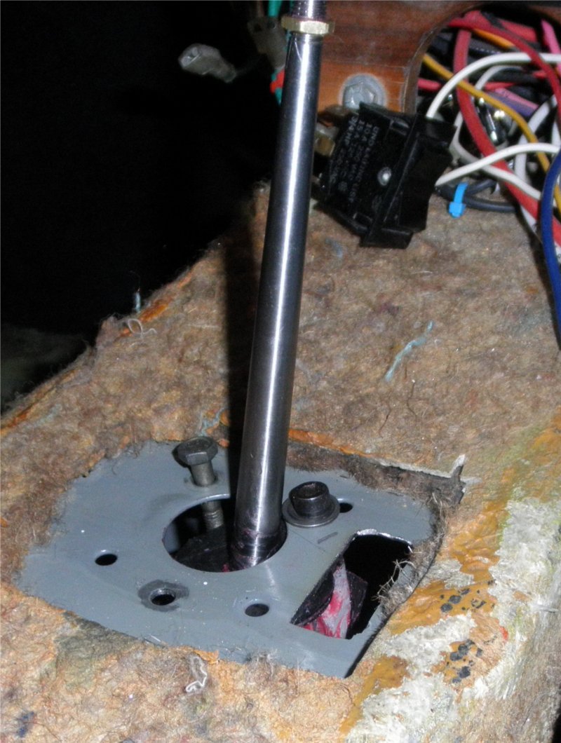
I don't have a picture of that screw in place (sorry). Here is a view from the top with the assembly loose in the tunnel. Leave it loose so you can turn things this way and that to access the rod ends and clevises. The picture is after the cables are attached. The red in the picture is synthetic grease, not blood!
In the following we see that I used moderately long bolts (6mm) to hold up the shifter assembly in the tunnel at times, but loosely. The 3rd temporary bolt (mentioned above) is invisible here. The black around the shift lever (inside the tunnel) is a 1.5 inch diameter piece of rubber which forms a nice dust shield while working. We'll leave it on the lever just above and outside the tunnel when we are done as extra dust protection.
The final picture relates to the big nuts that hold the cable sheath in place. I cut a 15/16ths wrench in pieces as short is useful in the tunnel and long wrenches are useless there! The cut on the box-end makes the box-end usable with cables attached already.
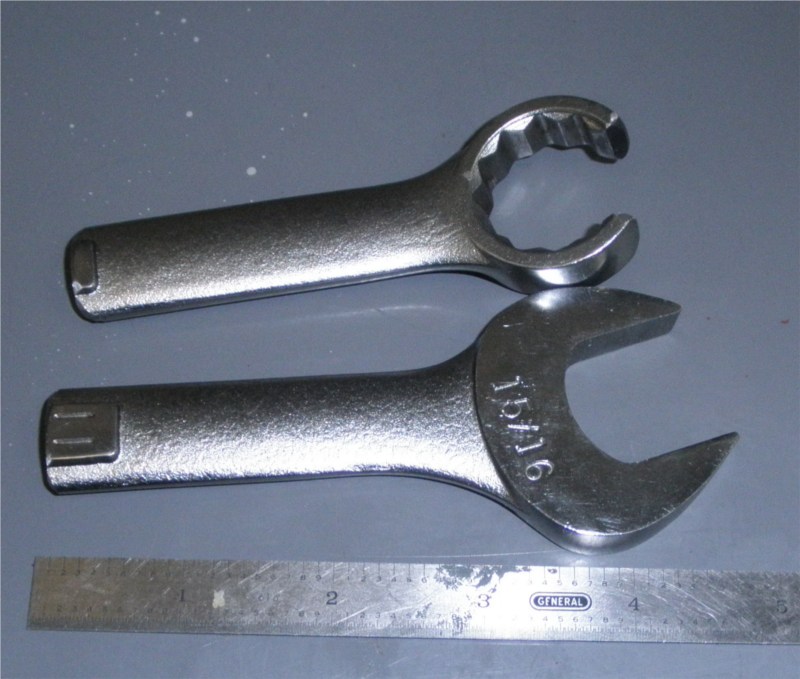
There is lots of fiddling in getting back together. Don't tighten the big cable nuts in the tunnel till after you have verified things shift properly and you like the position of the lever at rest. Get the nuts finger tight and then just tighten (in the tunnel) by turning the rear-most nut of each cable. The inner nut, you will observe, does not turn (you did cut those big holes so you can see the inner nuts, right?).
Before you try to screw the assembly to the tunnel top use a long 6mm screw in one of the front fixing holes (into the casting), let the thing down and remove the rearmost top screw and its big washer. Now pull up on the long 6mm screw and install two short (about 10mm) screws to fasten the shifter to the tunnel top. Now remove the long screw and put in a short one. And of course screw in the bracing screw in the standoff from the bracket to the tunnel-top. Now all that is needed is final testing and small adjustments. The effect of moving the cable-sheath nuts is larger than you think and counter-intuitive! Try things to get the shift right!
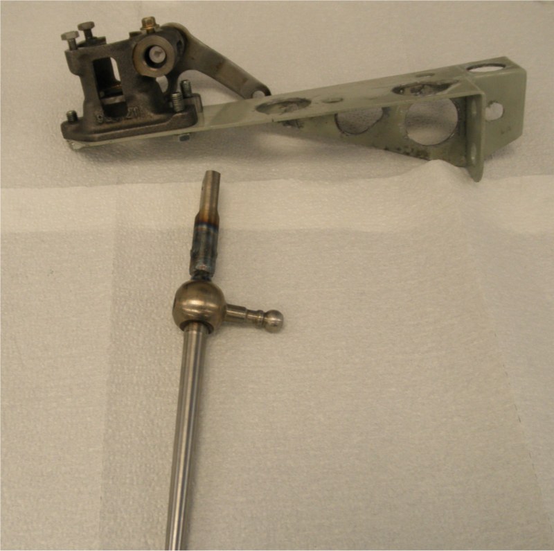
The shifter was working well in February 2012, but as shown in the picture, it has a very small threaded bottom that did not respond well to a ham-fisted driver at Mazda Laguna Seca turn 2 failing to match revs while trying desperately to shift to 3rd. I suspect the solution is welding directly to the bottom of the lever and keeping the diameter more like 10mm rather than the 5.5mm inner diameter of the threads. The rod end itself is sturdy enough, I suppose. The red is synthetic grease, not anything leaking from my fingers!
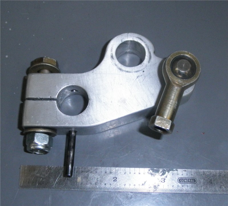
Nearly ready to be reinstalled in March 2012 with a new bottom to the shift lever and lightened parts (see next three pictures) I weighed the shifter and the cable shifter weighs 6.5 pounds. The Lotus-stock tubes and mechanism weighed 9 pounds, so the cable shifter is a 2.5 pound weight-saving. The pictures are before a final pass of removing burrs and painting. John Zender did the machining and welding for me. I apologize to Dave Lindemann for showing the wrong bolts here, I somehow have misplaced the original 6 small bolts he supplied so I'll have to do better before I install things.
One thing I noticed about the 90 degree piece that turns left-right shifter motion to fore-aft motion is that the original lengths of the two arms (not speaking of the round-rod which is the bearing surface) are in a ration of 2.3 to one. That is, 1mm of movement at the input-hole is 2.3mm of the output hole where the clevis attaches. By drilling a 0.25 inch hole up the one arm one can reduce the advantage to as little as 1.8 to 1. I decided not to reduce the mechanical advantage though.
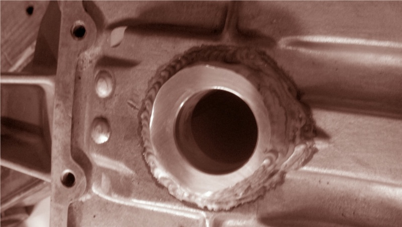
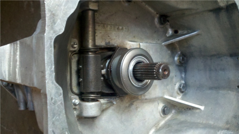
This is a work in progress picture of the welded-up and machined TC bell housing. The bearing and seal and spline-cover in a stock NG3 are a single unit available from Richard Winters, and they slip into the machined hole.
Like the previous TO bearing I used with the 336 transaxle, the TO bearing here is basically stock except that there is an extension piece to get the actual bearing out to the right place. We still use the original mechanical throw-out mechanism.
The exhaust is above the transmission (as it was with the 336 and Zetec) but it attaches to the transmission mount (as you can see near the top of this picture of the right side of the gearbox).
An appropriately sized hollow aluminum piece with a square-drive wire inside extends the (wide) magnetic pickup far enough to clear the gearbox and the cable shift.

This work is licensed under a
Creative Commons Attribution 4.0 International License.