| HOME | Software | Lotus Cars | DWARF | Kindle | Solar |
It took a long time to figure out how to make the clutch work. In the end it is all pretty simple, but all this was not obvious at the start. On the one hand, the bell housing is pretty much the stock TwinCam bell housing. On the other hand the Zetec flywheel is located closer to the block than the TwinCam flywheel.
The bell housing does have a dust shield, but it is not described here, see the starter page for dust shield information.
Like the bearing described below under "Original 336 Clutch Throwout" the NG3 is basically a stock throwout bearing mechanism with an extension piece. Barry Spencer created this as a part of the NG3 project.
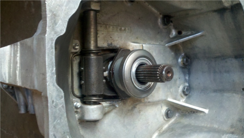
Then, in 2015, Barry found an input shaft which had a pilot bearing surface in his parts bin. This is what is in service as of 2018. It's not clear what Renault gearbox this input shaft came from. The splines and diameters match NG3/NG9 except for the seal area which had a collar added for my application (the seal collar just visible). The pilot shaft diameter matches what was done for the 336 zetec setup and uses exactly the pilot holder documented below. The picture is of a trial assembly, not final assembly.
The first task was to figure out what to do. Others had done this, but no one really had any details available. Even the very friendly folks on the Europa list had nothing specific to say. So I decided I needed to draw the system (2-D). In spite of the fact I had not done any 2-D drawing in 45 years and had never done any on computer. I knew there would be a steep learning curve, and I did not want to set up a drawing-board. No old-style for me :-) Since I run Linux the choices were very limited indeed. I chose qcad from www.ribbonsoft.com and overall I am satisfied with that choice.
The learning curve was steep. First you have to think in terms of vertical and horizontal line placement (of indeterminate length) and then pick out line intersections. Once you get used to it things seem natural, but it took me eight hours to do the first very simple thing... I no longer recall how long it took to do the first, simple, drawings. It took weeks. The best introductory documentation on qcad was translated from the French and not quite based on the same version of qcad! While the advice there was correct the small inconsistencies (compared to the qcad I was using) were maddening.
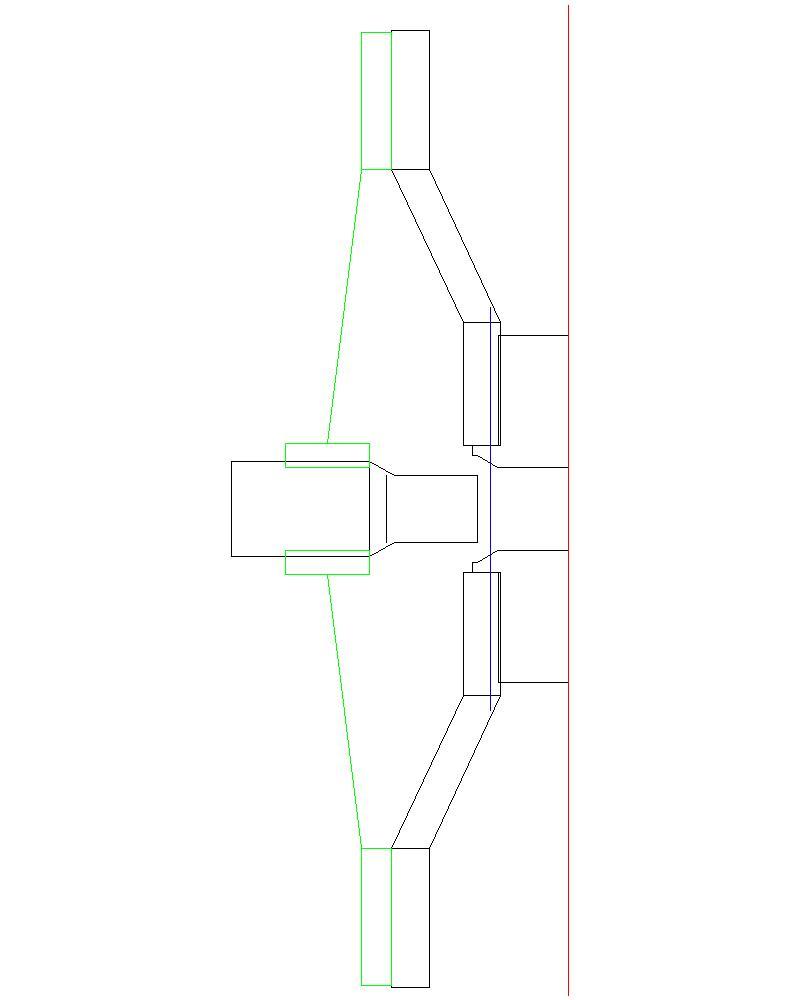
Eventually I had a pretty complete drawing with multiple layers so I could deal with each part separately or together. The following shows a picture of the inside of the bell housing with the transmission at the left (invisible) and the engine block at the right (but the block invisible too). The block edge is in red. A clutch is shown in green. The end of the input shaft is shown in black. The end of the crankshaft and the Fidanze flywheel (the parts we care about here) are in black.
The clutch disk itself is 240mm diameter, a stock Focus diameter.
Notice the end of the transmission input shaft does not reach the crankshaft. So unless we provide an extension to the flywheel or a longer inputshaft we have a problem as nothing prevents the inputshaft from wobbling.
I designed a crankshaft extension. Because the transmission input shaft nose is longer than needed for the TwinCam yet long enough to limit the thickness of the extension I shortened the input shaft slightly (less than 0.20 inches). It winds up with the shaft-end about 16-17 mm long.
The following is pretty close to what was made. The end of the crankshaft is 0.825 inches precisely. The piece was made of an easy-machining stainless steel to about 0.8253 inches diameter. By a master machinist, not me. The bushing was 16 millimeters long and pressed in and machined to 17mm internal diameter. After assembling the transmission on the car I realized the piece needed shortening by about 3 or 4 mm, so I removed that much from the left side (as viewed) so the clutch disk would not touch the piece. The extension is smaller than the boss on the flywheel so it fits through the center hole of the flywheel easily.
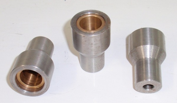
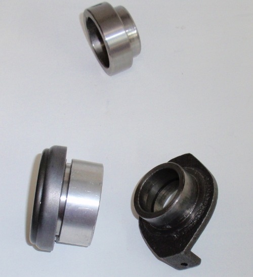
A picture with three samples of crank extensions follow, these are not in final form. The actual bushing in there is a 16mm long, 22mm od, 16mm id bushing. McMaster-carr (mcmaster.com) items like 7811 K34, 6658 K34 could be used. In the end I am not quite positive which bronze alloy I used in the piece in service (oops).
You might think I could have used a Zetec pilot bearing such as for the Ford Escape 2001-2005: NAPA FC65354. The OD of that presses into the Zetec crankshaft id of 0.825 inches, so the extension ID would have to match. But the ID of that is not the 17mm the stock Renault input shaft needs. So, no, that is useless in this application (unless one has a different input shaft, and in that case why not have the shaft made long enough to reach the crank and fit the pilot bearing in the crankshaft?).
The following is a drawing of the extension as created. It has one defect: the left end step is 20mm long and the bush is 16mm long. It turns out that you really want the extension shortened (at the left) to the 16mm of the bush. And with a shortened input shaft nose the inner step (to 0.941 inches on the drawing) is not needed. Here is the original drawing as I had it made (not showing the bush itself), but be warned: all of the +- limits on the dimensions are kind of bogus and the machinist ignored them and did his own thing.
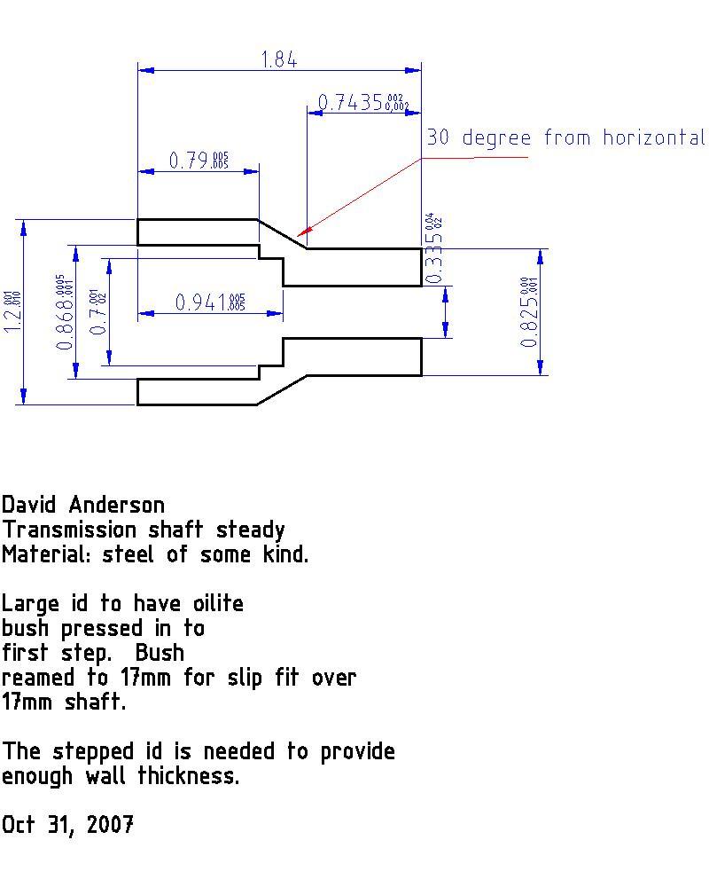
The only critical dimensions here are the diameter of the press fit into the crankshaft, the press fit of the bush into the steel, and the 17mm that the bush must be reamed to.
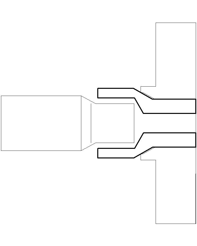
Since the above is a bit out of date, I redrew the relevant bits. First I show how the end of inputshaft (shorted to 16m long pilot bearing length) and the simplified extension go together (I do not show the bronze bearing, hence the gap between input shaft and the extension).
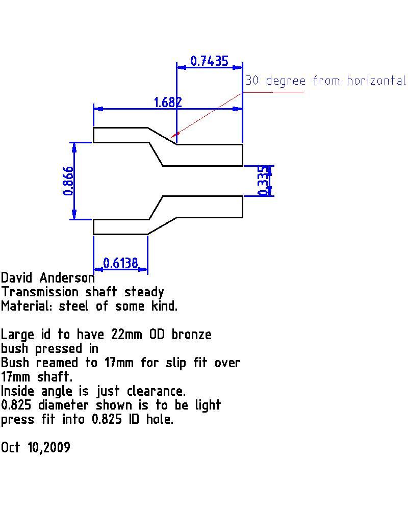
Here are the dimensions of the revised crankshaft extension.
There was another possibility, one I did not think of till 2009: make an input-shaft extension. Press fit on the inputshaft and fit into a Ford Escape pilot bearing in the crankshaft. Lighter weight than pressing into the crank. The only downside would be that the inputshaft has to be removed from the transmission to press on the piece. But that removal is the right way to shorten the existing shaft anyway (and shortening is really desirable for any approach here).
It seemed (using a Ford Focus pressure plate) I needed to extend the stock 336 throwout bearing. So I had a simple aluminum extender made, the total extension beyond the stock was 0.75 inch. Once I switched to a CenterForce pressure plate (to fix a clutch slipping problem) I found the pressure plate fingers were too close so I had no adjustment.
The pressure plate is from DownsMotorSports.com, CenterForce clutch kit for ZX3 and ZX5, part number M-7563-Z3. It comes with a nice clutch disk but that has Ford splines so I could not use it (yet).
I reduced the cast iron holder and the aluminum extension so the extension was about 0.2 inch less, so the extension beyond stock was around 0.55 inch. Then the CenterForce and my throwout bearing worked together just fine.
The picture below is a stock cast iron throw-out bearing holder and a couple of the extensions I had made (one with bearing attached). These give an idea of how things looked (these have not been 'reduced', just left as is).
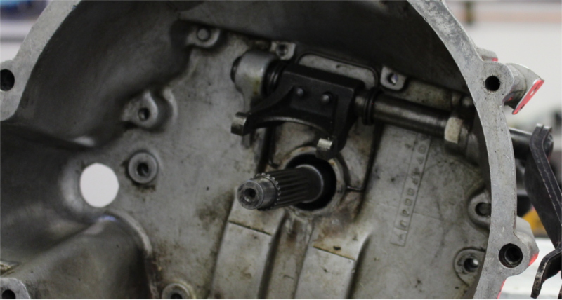
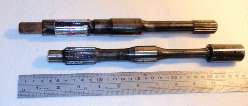
The following picture is of two transmission inputshafts. The upper is an NG3 (with a wooden extension on the front, this is a mockup, not a real working shaft) and the lower is 336 (with the spline-coupling left on). Lined up at the ends of the respective shafts. Note that the NG3 is set up for use with Zetec: long enough to reach the crankshaft and with the correct diameter to interface with the crankshaft and the Ford Escape pilot bearing mentioned above! Webster Gears made real input shafts like the extended-nose NG3 version but never created an actual parts diagram. Then they moved from Mill Valley, CA to Texas. So this route got abandoned.

This work is licensed under a
Creative Commons Attribution 4.0 International License.