| HOME | Software | Lotus Cars | DWARF | Kindle | Solar |
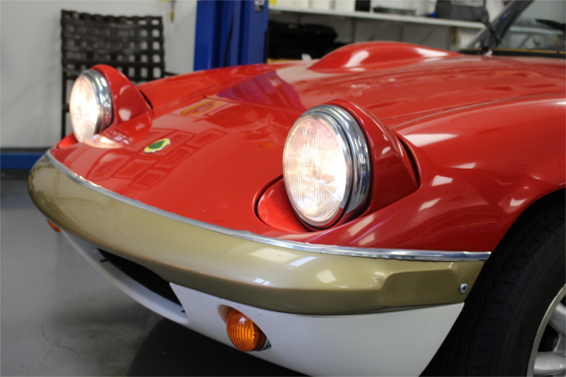
Beginning with the Elan Series 3 the mechanism for raising/lowering the headlights became the 'Safety Headlight' system. Safety meaning that if the vacuum system for raising/lowering the headlights failed the headlights would be 'up' and night driving would be fine.
Earlier Elan headlights would, if the vacuum system failed, stay down making night driving unsafe! Early cars used two bellows where the late ones needed just one bellows.
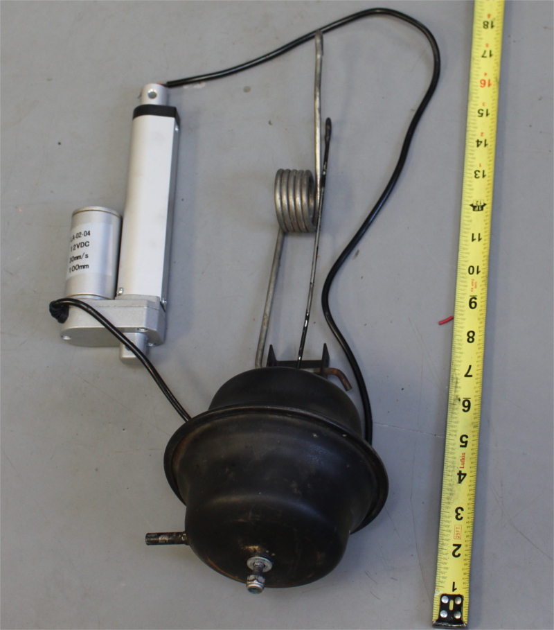
The vacuum system involved lots of plastic tube and plenty of rubber/plastic joints and the front frame area (a big box) was sealed to be the vacuum reservoir. A big rubber bellows (in a can), a big spring near the bellows, a vacuum switch on the dashboard, and a one-way valve connected to the intake manifold of the engine were the system.
If any of those areas leaked air the safety headlights would slowly pop up (in a quiet garage my Elan made groaning sounds for hours while the lights slowly rose). It was difficult to diagnose the leaks. Here is the rubber bellows assembly alongside the linear motor..
So a fellow Golden Gate Lotus Club member, Gale E., put a video of changing the headlight raising to use a linear motor on youtube. Thus no longer using the vacuum system.
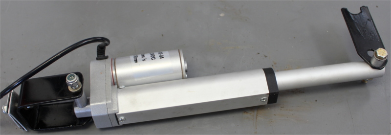
The following is the story of changing the system to use a linear motor. Here is the motor portion with most relevant parts attached.
The two big issues in installing were
The motor has two wires and uses a maximum of 6.5Amp at 12 V.. Depending on which wire is positive and which is negative the motor with either extend 100mm or contract 100mm. Once it reaches its limit it just stops. The wiring sets up the linear motor to always be powered, though it won't draw power once it reaches the desired limit.
Like Gale E, I wired it so the direction of motion is via a switch-to ground of the control part of the circuit. The motor is always powered and the switch controls, via the relay, which motor wire is postive and which is negative. For positive, I took power from the back of the cigarette lighter, into a 7.5Amp fuse, and then to the relay. For Negative the always-live goes to ground near the cigarette lighter. The switching negative is is switched by the original headlight switch (more on this later).
The actuator system wiring diagram shows the wiring schematic. All wires are 18 ga. All the wiring is at the dash except for two wires that go through the firewall and around the radiator to the motor. The only place there was room for the 8pin relay was at the right side of the behind the cigarette lighter and under the header box.
The switched negative uses the multipurpose switch at the lower-left of the center console. The car was restored as an S4 in 1994 so the wiring by the headlights is complicated. This switch controls a vacuum switch and two electrical switches all riveted together.. The upper electrical switch ensures that running lights are on when the headlights are on: this is unchanged. The lower electrical switch provides a ground (when headlights on) to the relays near the headlights that either turn on high or low beams. The change I made was to add a 1-to-2 spade connector so the lower switch grounds both the headlight relay appropriate and grounds the new 8-pin motor relay. If that makes any sense. The result is turning the headlights on/off by the original push-pull switch also raises/lowers the headlights electrically. Here is the relay, exposed.
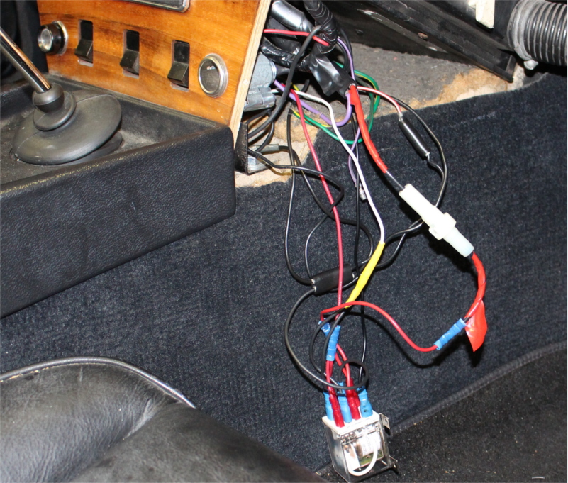
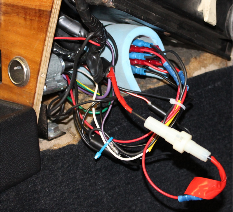
Here is the relay where it rests. The blue foam is to keep it from rattling around. The exposed purple/black bullet terminal is not related to the relay and got covered after the photo.
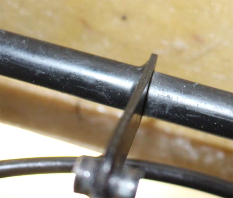
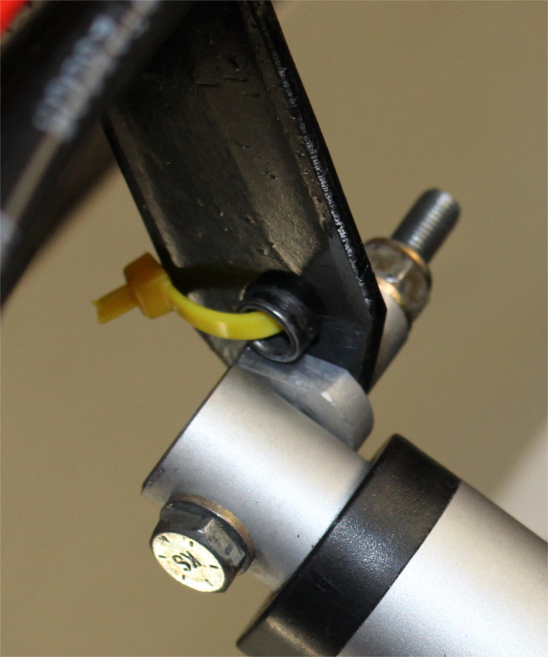
All dimensions in inches and surely not correct to 0.001 inches. Maybe correct within 0.01 inches? The tube here is the cross-tube welded into the bracket extending out from the bar. See the following photo.
| Bar OD | 0.643 |
| Tube OD | 0.386 |
| Bar to tube (at the OD of each) | 3.0 |
| Center to Center:Bar to tube | 2.49: maybe really 2.5 |
With the vacuum parts removed it becomes possible to measure the existing motion to raise/lower the headlights. The factory raise/lower bracket where the spring rests moves, by my measurements, 2.85 in from fully up to fully down.
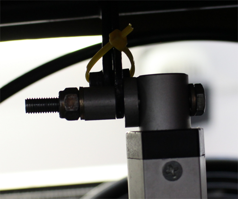
That does not match the linear motor travel of 4 in.! So following Gale E, I made a simple steel bracket to extend the attachment point. The open end slips over the crossbar. The big hole slips over the stock tube used for the spring attachment. The small hole is just out past the end of the original Lotusbracket welded to the crossbar. The farther out you put the new hole the longer the new stroke will be. This hole location is fairly critical, though great precision is not really required. The hole being just past the end of the stock bracket results in a movement at the hole of 3.85 in when going through the full motion of the headlights.. That seems close enough. The motor and the headlights seem to be fine at 3.85 given a little bit of slop surely exists in the system.
The upper bracket is made of the same stell bar stock as the lower bracket and it was shaped with a drill and some filing.
Another picture, looking from the front grill upward toward the cross bar.

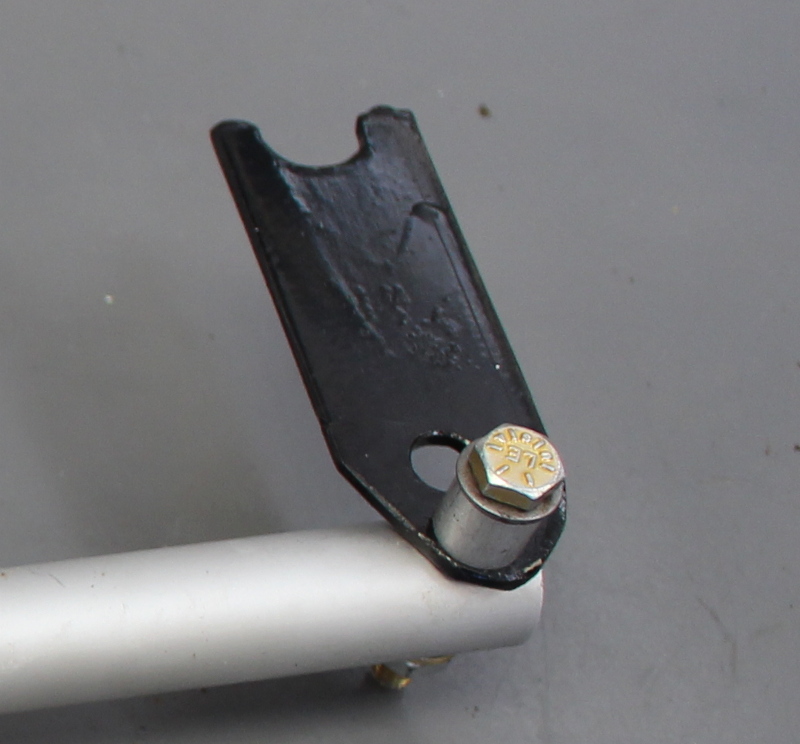
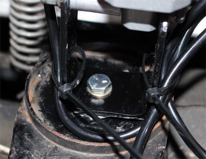
The lower bracket is simple and no great precision is required. By ensuring it is just a little short one can use simple flat shims under it for final adjustment. I finally used three shims cut from 0.040 in thick aluminum I had on hand.
How it looks on the bench.
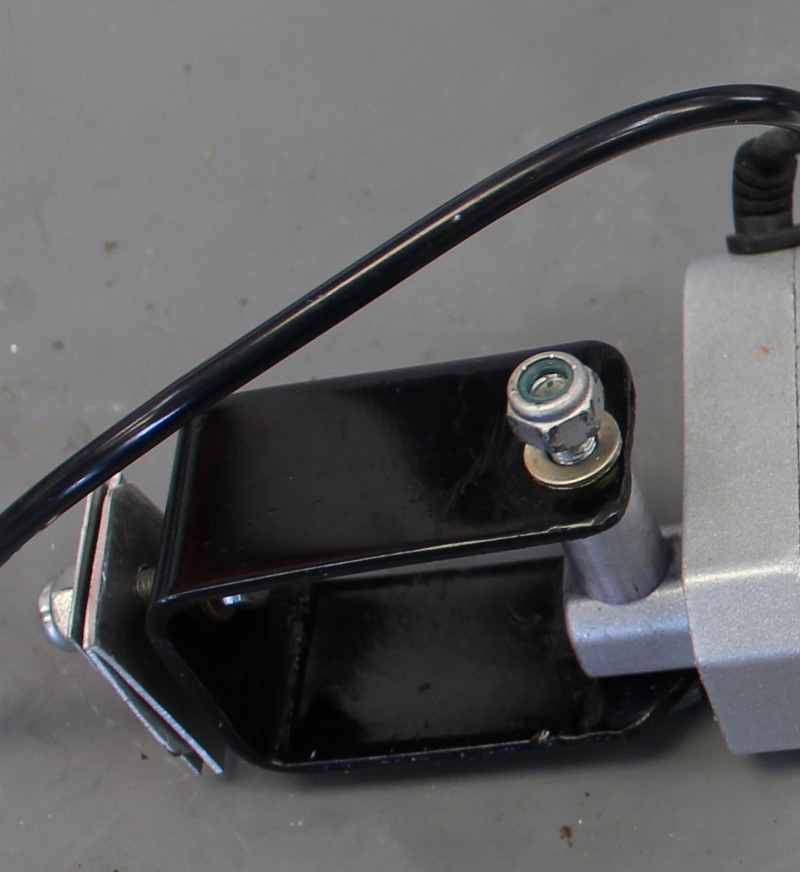
How it looks as installed (next two photos).
The yellow tie-wrap does little, really, but if the bolt is undone that will keep the new piece from falling off. It's slightly puzzling how sturdy it is.
| name | description | source | approximate cost |
|---|---|---|---|
| upper bracket | Connects headlight bar to linear motor | Steel bar 1/8in. by 1.25in cut to length | Under $1 |
| Linear Motor | Moves the headlights | LA-02-04 from Tampa Motions | About $75 |
| 12v Relay | controls power to motor | 8 pin DC 12V DPDT relay | About $8 |
| lower bracket | Mounts motor to body | Steel bar 1/8in by 1.25 in by about 8 in | Under $2 |
| two bolts | 1/4-28x2.5 bolts mounting motor | Grade 5 | Under $1 |
| bolt | connect bracket to body | one 1/4-28x1 bolt | Under $1 |
| washers/spacers | as needed | hardware store | Under $1 |

This work is licensed under a
Creative Commons Attribution 4.0 International License.