| HOME | Software | Lotus Cars | DWARF | Kindle | Solar |
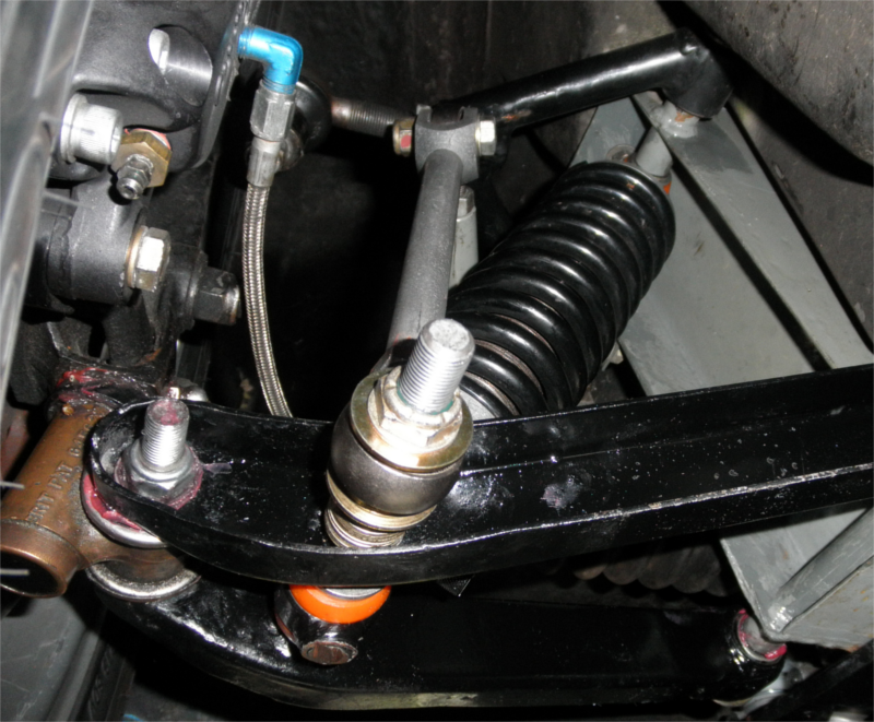
The following picture is as of December 12, 2012. See other pages here for more on the brakes and sway bar (sway bar and shock (damper) disconnected in this picture).
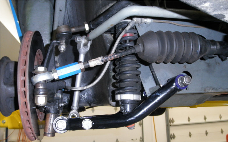
There is nothing wrong with the stock front suspension, but a few years ago I installed a Dave Bean upper A-arm to get camber adjustability. Then in late November 2012 I discovered that the right lower shock (damper) mount was broken. It was an assembly error on my part that pushed the arms apart (or tried to) and tore the lower front arm shock-mount hole loose from the arm. Still perfectly safe (all was held together) but my goodness, not what anyone would knowingly drive on. Well, original lower A arms are no longer available. Dave Bean had nothing available. Ray, at rdent.com, has had some created as well as some urethane bushings. So I bought new A arms and bushings. Well, as you will read below I used those for one trackday and then went back to stock arms...
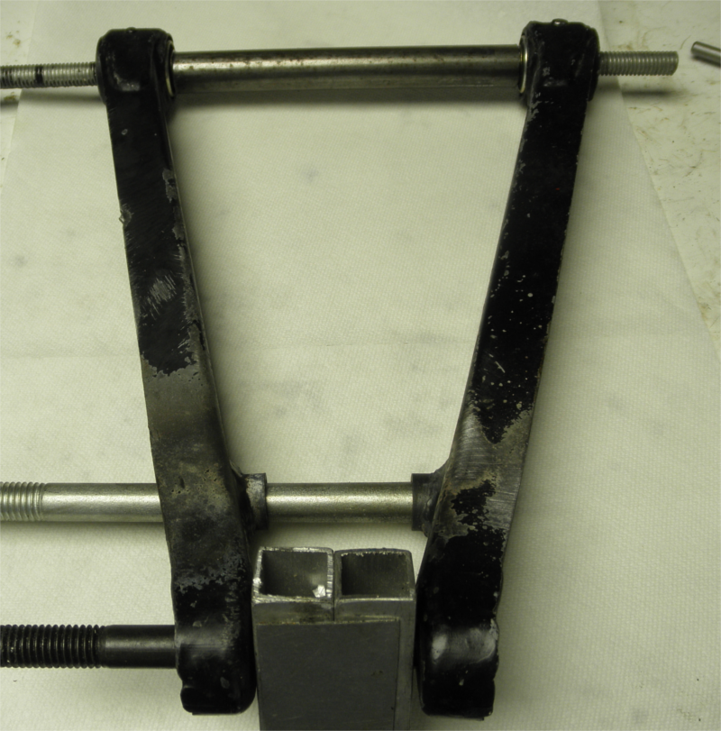
UPDATE 05 September 2013 Following the discovery that the aftermarket lower a-arms were bent (see below, the 30 August update), I had the small issue with the stock a-arm rewelded and I am installing the original a-arms. To do that properly I used some tooling (some new) to make the setup easier to check and measure. I install new bushings though the old ones were probably usable. The tools shown are perfect for removing old bushings and installing new ones.
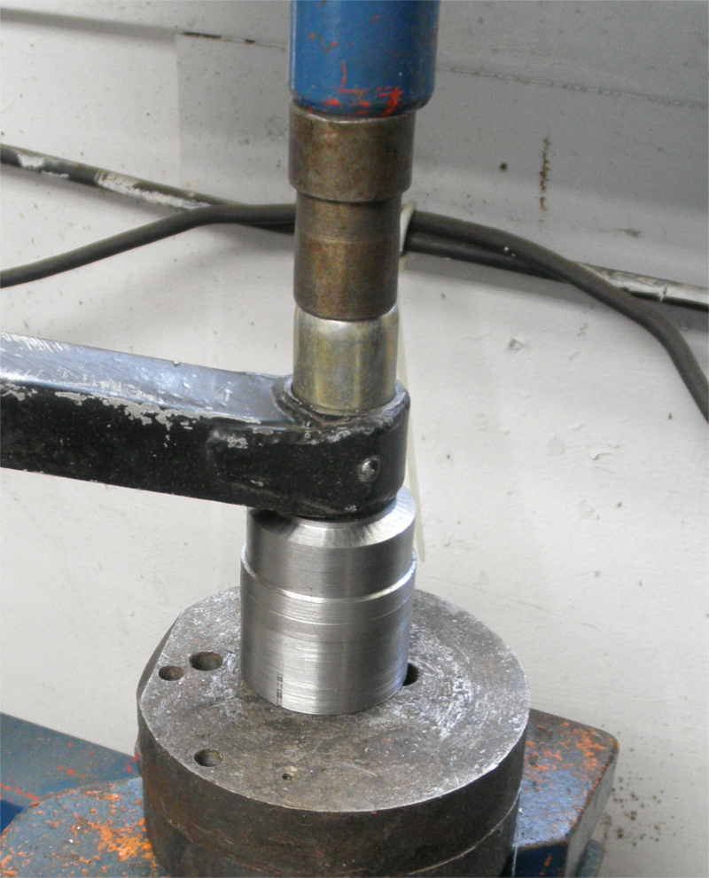
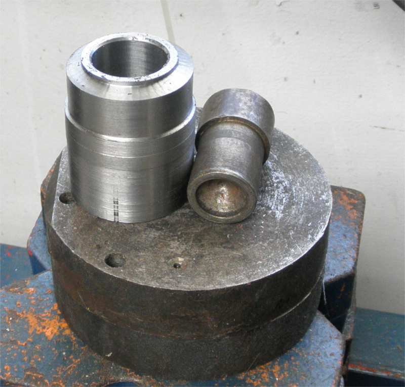
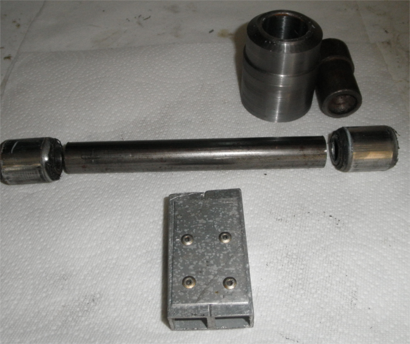
Here are the install tools. (See the picture just above to see the tools in use). The smaller one (lying down) a pusher (fits through the bushing area of the a-arm) and the bigger tool the base (room for the bushing while supporting the a-arm in either up or down orientation). A 12-ton press with these tools suffices to make bushing removal and install easy. The picture is before I painted them a brilliant rattle-can blue!
Here is the stock left front suspension arms with stock bushings. The red is grease I should clean up. The big washers at the inner end are overkill, for safety.
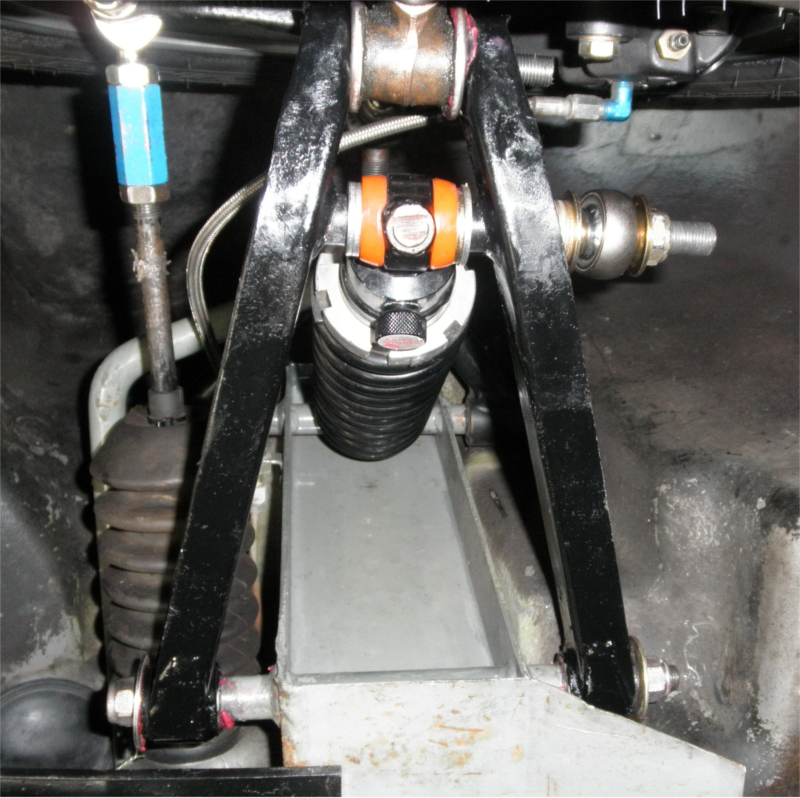
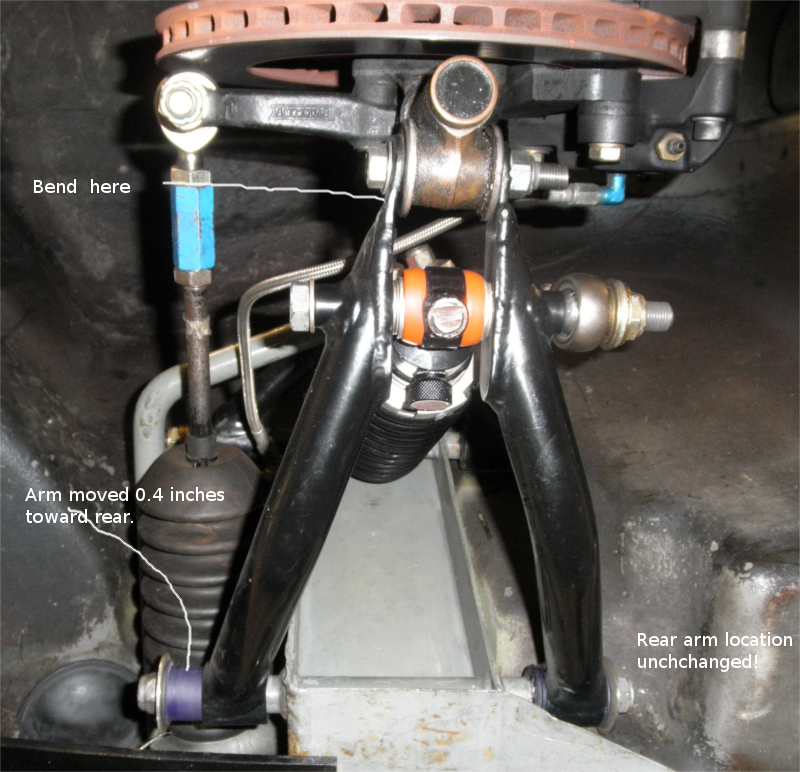
Here is the stock left front lower suspension arms and the adjustable top a arm from the rear a bit so the anti-sway bar connection is clearer.
The top of the pusher is just a pad for the press to work on. The bottom area of the pusher are the only pusher dimensions shown The Pusher working hole depth is, of course, to ensure the pusher works only against the outer steel shell of the bushing. The Base ID lets a bush slide in and out easily (no friction, no touching the sides). The Base Depth has to be deep enough to hold an entire bushing.
| Description | Inches |
|---|---|
| Pusher bottom | |
| Pusher working OD | 1.04 |
| Pusher working ID | 0.75 |
| Pusher working Hole Depth | 1.72 |
| Pusher working height | 1.25 |
| Base | |
| Base ID | 1.40 |
| Base OD at top | 1.10 |
| Base Hole Depth | 1.90 |
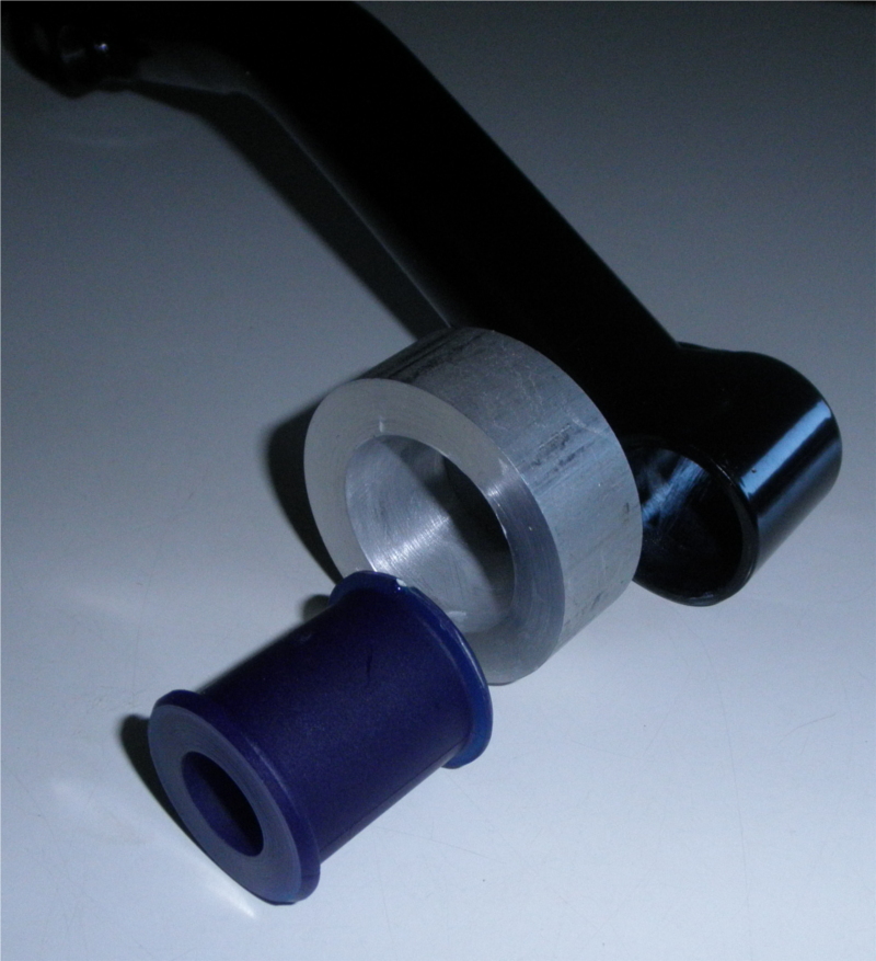
Once bushings installed, one can place the parts on the bench to verify it all fits. Now 'fits' is a relative word. In the picture a hollow rod plays the role of the frame and the rectangular aluminum plays the part of the trunnion. Note that the right hand bushing is not quite parallel to the rod but the left bushing is. That means (to me) that the factory allowed plenty of tolerance in the creation of the a-arms, with the tolerance taken up by the bushing rubber as installed.
The upper tools here are for bushing install and removal. The middle is the hollow rod to stand in for the frame when looking at alignment on the bench (along with a couple used suspension bushings). The lower piece is scrap aluminum with a through-hole to play the role of the trunnion while the arms are on the bench. All these got painted blue after the picture...
The inch dimensions below (of the gap from front to rear lower front a-arms) should be taken as reasonably accurate, but not accurate to closer than say 0.020 inch. The frame-tube gap seems odd, perhaps I am measuring the 0.010 due to paint on the end of the tubes.
| Description | Width,Inches |
|---|---|
| Frame Tube | 6.010 |
| Shock Mount LH susp | 1.715 |
| Shock Mount RH susp | 1.690 |
| Trunnion Mount | 1.490 |
UPDATE 30 August 2013 following Aug 3 track day! During the after-track-day inspection I discovered that the front lower a-arm was bent. Though Ray has not heard of problems, a friend with the same a-arms (not bought from Ray) had (subject to verification) the same problem. I also abandoned the urethane bushings and went back to the stock bushings because there is a pretty strong locating force from the stock bushings. Even though the originals are more difficult to install (but with the proper tooling as shown on this page the originals are actually easy to install).
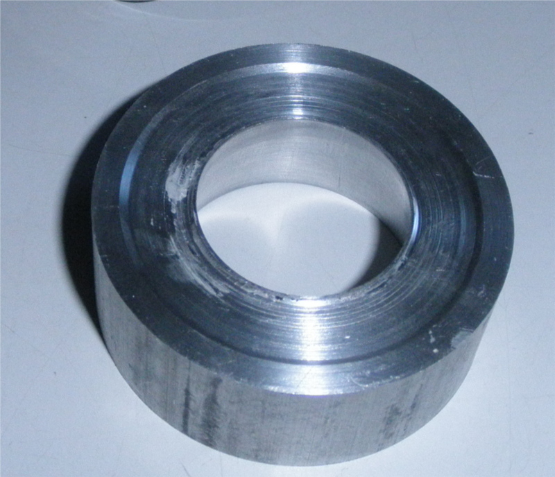
The instructions said to push the urethane in by hand. I was getting nowhere! So instead of asking Ray how to proceed (no doubt he had good advice, but who needs advice :-), I created an aluminum tool with a tapered hole so the bush could be fully inserted and pressed into the a-arm with light application of a vise.
The bottom of the tool has a cut so keeping the tool centered on the a-arm hole is easy.
After the bush was installed it looks like this:
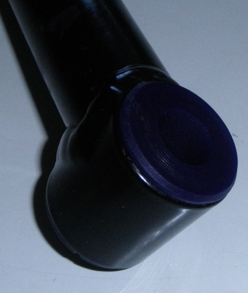
With the bush installed, pushing the steel inner tube into the urethane was simple -- again using a vise.

This work is licensed under a
Creative Commons Attribution 4.0 International License.